You have been using 'No Flow' boundary conditions for all the GSSHA models that you have created so far. In this assignment you will learn how to define ‘hydrograph’ boundary condition in Provo Canyon model and ‘variable stage (water surface elevation)’ boundary condition in the Galveston, TX model.
Hydrograph Boundary Condition
You will use Rock Canyon watershed model to see how 'hydrograph' boundary condition works. This scenario is actually two models used in conjunction. The portion of the watershed upstream of the city of Provo, Utah was first modeled as a lumped-parameter model using HEC-HMS which resulted in a hydrograph with a peak discharge of 78 cms and a runoff volume of 850,000 cubic meters.
The current project is a GSSHA model developed for Provo area. You will use the hydrograph from the upstream HEC-HMS model (provided here) as an inflow hydrograph into the GSSHA model at the stream node furthest upstream, located nearly on the boundary of the model.
The model boundary shown in the upper right side ( See above figure) coincides with the outlet of the previously developed regional model. For the local (GSSHA) model, the inflow hydrograph is the only source of water. Because a precipitation event of some form is required by GSSHA, a uniform event with an intensity of 0.01 mm/hr and a duration of 10 minutes will be used. This amount of rainfall results in no significant amount of overland runoff, therefore any overland flow present in the results of the model is from water flowing out of the channel.
Download and open the base GSSHA model for this project. Select Edit | Current Coordinates and make sure the coordinates are UTM NAD 83, Zone 12
Base Model Topo map Inflow Hydrograph (cms)
Follow these instructions to define the hydrograph boundary condition:
This project demonstrates how the overland boundary conditions capability in GSSHA is used to model coastal storm surges after a cyclone event. The site is located in Galveston Island, Texas as shown in figure below. As we are not simulating overland flow, the watershed doesn’t have an outlet location where outflow will be measured; instead, it has boundary conditions. Because the northern section of the island is the most populated, this was the area used for the model.
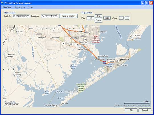
Figure 1 : Watershed Area
The boundary conditions will be defined to represent the storm surge caused by Hurricane Ike on Galveston Island in September 2008. Ike's large wind swath, along with the fact that it piled water over the shallowest portion of the Gulf, lead to much higher than normal storm surge flooding along the Upper Texas and Louisiana Coasts.
The following three boundary conditions will be used here:
- Variable Stage BC on the gulf side of the island
- Variable Stave BC on the bay side of the island
- Download and open the GSSHA project Galveston.prj
Figure 2: Boundary conditions
- Download and open the base GSSHA project. This model uses 150 by 150 m grid cell. All the parameters including the precipitation have already been defined for you. This model is similar to other GSSHA models you have been creating this semester (i.e. with all 'No Flow' boundary).
- Select Edit | Current Coordinates and make sure the coordinates are UTM NAD 83, Zone 15
- Save the project to your working folder and run it to make sure everything is wroking.
The following steps help you define the boundary conditions.
- Using the topo map and above figure as a guide, create an embankment arc where the levee surrounding Old Fort San Jacinto is located (north of Galveston Island). Double click the embankment arcs, change the type to ‘Embankment’ and click on the Browse button under Embankment. In the Embankment Arc Profile Editor dialog, enter 6 for PVI elevation and click Compute Vertical Curve. This will set embankment height to 6 m.
- Also create an embankment arc where the seawall goes inland (behind Stewart Beach Park in the northeast section of the island). In the embankment dialog box, set embankment height to 6 m. Make sure that the two embankments don’t overlap (see inset image in above figure).
- Create a node in the start point and end point of your Gulf Boundary arc as shown in Figure 3. Select both the arcs represented by red line and set the arc attributes to ‘variable stage (water surface elevation)’ under Flow BC type field. Click on Browse button under Variable Stage BC and enter the Galveston Pleasure Pier storm surge time series into the XY series editor. The time series can be found here.
- Create a node in the start point and end point of your Bay Boundary arc as shown in Figure 3. Include a node in the middle where the watershed outlet is located. Select both the arcs represented by blue line and set your arc attributes to variable depth and enter the Galveston Pier 21 storm surge time series into the XY series data editor. Get the time series data here.
.
Figure 3: Node locations
- Save your model.
- Run the model checker to make sure there are no errors in your model.
- Run the GSSHA simulation (using GSSHA 5.0).
- Get the sceeenshots of the results.
- Create an animation filmloop using this model and open the KMZ animation file in Google Earth.
.
To Turn in
Create a summary report about your observations and learnings from these two projects. What might be the possible applications of such type of models? Do not forget to include the screenshots of the results in your report.
Email the link for your homework page to the TA.
*****